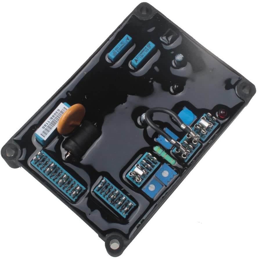
AVR AS480 for Stamford Generator
- AS480 is a half-wave phase-controlled AVR
- Sensing and Power Input: Voltage 100-264 Vac 1 phase
- Output:Voltage: 82 V dc @ 200 Vac input voltage
- Output:Voltage: 45 V dc @ 110 Vac input voltage
- Frequency: 50-60 Hz Nominal
- Regulation:+/- 1.0%
- Click Here To Download AS480 User Manual
₨ 28,000.00 ₨ 30,000.00
Buy all Stamford AVRs and Rotating Rectifier assemblies in Pakistan. You can buy AVR AS480 for Stamford Generator online anywhere from Pakistan or by visiting Electronic Power House(EPH) andTetralink Technologies(TLT) in Lahore who are the main distributor of Stamford in Pakistan. All original Stamford products are available at very reasonable and best prices in Pakistan
Key Features:
- AS480 is a half-wave phase-controlled AVR
- Sensing and Power Input: Voltage 100-264 Vac 1 phase
- Output:Voltage: 82 V dc @ 200 Vac input voltage
- Output:Voltage: 45 V dc @ 110 Vac input voltage
- Frequency: 50-60 Hz Nominal
- Regulation:+/- 1.0%
General description
AVR AS480 for Stamford Generator is a half-wave phase-controlled AVR which forms part of the excitation system of the brushless generator. The design employs Surface Mount Technology (SMT), custom moldings, and heatsinks to produce a compact AVR assembly. The AVR also incorporates an interface to the optional Excitation Boost System (EBS) for use where short-circuit current maintenance is required.
The AVR is linked with the main stator windings and the exciter field windings to provide closed-loop control of the output voltage with load regulation of +/- 1.0%. The AVR voltage sensing terminals continuously sample the output windings for voltage control purposes. In response to this sample voltage, the AVR controls the power fed to the exciter field, and hence the main field, to maintain the machine output voltage within the specified limits, compensating for load, speed, temperature, and power factor of the generator.
Positive voltage builds up from residual levels is ensured by the use of efficient semiconductors in the power circuitry of the AVR.
A frequency measuring circuit continually monitors the
generator output frequency and provides under-speed protection of the excitation system. This is done by reducing the output voltage proportionally with speed below a pre-settable threshold. A manual adjustment is provided for the factory setting of the under frequency roll-off point, (UFRO). This can be changed to 60Hz (or 50Hz) in the field by push-on link selection.
A wide range of stability settings is available to compensate for machine sizes and applications. A slow setting is available for applications involving single/twin-cylinder engines and where lamp-flicker could be a problem.
Provision is made for the connection of a remote voltage trimmer, allowing the user fine control of the generators output voltage.
Operation with 110Vac sensing is possible, replace the hand trimmer link with a fixed resistor. The hand trimmer option cannot be used in this configuration. The generator overload capability is reduced in 110V operation.
The AVR AS480 for Stamford Generator has the facility for droop CT connection, to allow parallel running with other similarly equipped generators.
Over excitation conditions are limited to a safe period by a protection circuit within the AVR. Once activated by a sustained over-excitation condition, the generator voltage is reduced to a low level until reset. Stopping the generator or removing power from the AVR will perform the necessary reset.
Connections are provided to interface to the optional Excitation Boost System. This incorporates a small externally mounted rotary power supply which provides excitation power in the event of heavy overloads or short circuits. The EBS is short term rated and responds to signals from the AVR to deliver excitation power when required. A separate overload protection system within the EBS electronic module protects the generator against sustained overloads.
The AVR Circuit Description
The main functions of the AVR AS480 for Stamford Generator are:
Sensing Voltage Divider / Adjust takes a proportion of the generator output voltage and attenuates it. The potential divider is adjustable by the AVR Volts potentiometer and external hand trimmer (when fitted). The output from the droop CT is also added to this signal. A Precision Rectifier converts the a.c. input signal into d.c. for further processing.
The Amplifier compares the sensed voltage to the Reference Voltage and amplifies the difference (error) to provide a controlling signal for the power devices. The Ramp Generator and Level Detector and Level Shifter infinitely control the conduction period of the AVR Output Power Control devices. This provides the exciter field windings with the variable power necessary to maintain the generator voltage within specified limits.
The Stability Circuit provides adjustable feedback to ensure good steady-state and transient performance of the control system.
The Low Hz Detector measures the period of each electrical cycle and causes the reference voltage to be reduced approximately linearly with speed below a pre-settable threshold. A Light Emitting Diode gives an indication that the circuit is activated by the low-speed running condition.
The Synchronising circuit is used to keep the Ramp Generator and Low Hz Detector locked to the generator waveform period. The Low Pass Filter prevents distorted waveforms from affecting the operation of the AVR control circuit.
AVR Output Power Control devices vary the amount of exciter field current in response to the error signal produced by the Amplifier.
Input Power Suppression components are included to prevent load generated voltage transients from damaging the AVR components and also to reduce the amount of conducted radio-frequency noise on the generator terminals.
The Over Excitation Detector continuously monitors the exciter field voltage and provides the signal required to collapse the output voltage. This protection circuit triggers only if an over-excitation condition persists for a specific amount of time.
The Power Supply provides the required voltages for the AVR circuitry.
The EBS Interface provides the signals necessary to control the excitation boost generator (EBG). The EBG responds to the level of excitation provided by the AVR and supplies additional power as it is needed to support the overload.
| brands | STAMFORD |
|---|---|
| color | Black |
Technical Specification
SENSING and POWER INPUT
Voltage? ?100-264 V ac 1 phase Frequency? ? ?50-60 Hz nominal
OUTPUT
Voltage? ? ? 82 V d.c. @ 200 Va.c power input. Voltage? ? ? 45 V d.c. @ 110 Va.c power input.
Current? ? continuous 5A (see note 1). transient 7.5A for 10 secs.
Resistance? ?15 ohms min
REGULATION
+/- 1.0% (see note 2)
THERMAL DRIFT
0.03% per deg. C change in AVR ambient (see note 3)
TYPICAL SYSTEM RESPONSE
AVR response?????????????????????????????????? 20ms
Field current to 90%???????????????????????? 80 ms
Machine Volts to 97%?????????????????????? 300ms
EXTERNAL VOLTAGE ADJUSTMENT
+/-10% with 1 k ohm 1 watt trimmer (see note 4) Increasing resistance lowers voltage.
Fixed 15kOhm resistor enables 110V sensing
UNDER FREQUENCY PROTECTION
Set point??????????????? 94 -98% Hz (see note 5)
UNIT POWER DISSIPATION
12 watts maximum
BUILD UP VOLTAGE
4 Volts @ AVR terminals
QUADRATURE DROOP INPUT
10 ohms burden
Max. sensitivity: 0.07 A for 5% droop 0PF Max. input: 0.33 A
OVER EXCITATION PROTECTION
Set point?????????? 67 Vdc +/-3% (fixed) Time delay?????????? 10-15 seconds (fixed)
ENVIRONMENTAL
Vibration?????????? 20-100 Hz??????????? 50mm/sec
100Hz ? 2kHz????? 3.3g
Operating temperature???????????????? -40 to +70C (note 6)
Relative Humidity 0-70C????????????? 95% (note 7)
Storage temperature??????????????????? -55 to +80C
Based on 0 reviews
Be the first to review “AVR AS480 for Stamford Generator”
Related products
-
Automatic Voltage Regulators (AVRs)
AVR R449 Automatic Voltage Regulator For Generator of Leroy Somer
-23%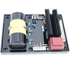 Automatic Voltage Regulators (AVRs)
AVR R449 Automatic Voltage Regulator For Generator of Leroy Somer
Key Features
- 100% Brand New And High Quality.
- Capable of withstanding harsh conditions and high vibration levels.
- Vibrations: -10Hz – a half-peak amplitude of 2mm; 10-100Hz – 100mm/s; +100Hz – 8g. Can operate in temperature extremes (-30c to +65c)
- Automatic Voltage Regulator R449 R replaces Leroy Somer R449.
- Voltage regulation +/- 0.5 % at steady state and constant speed.
- Two-phase voltage sensing.
- Control by transistor means the regulation quality is independent of load applied.
- Integrated “LAM” system to cope with increased loads applied to the engine
- We are confident the quality of our product is 100% qualified. If there is any question, feel free to contact us. We will offer the best service for you. Thank you!
- Click Here To Download R449 User Manual
SKU: n/a -
Automatic Voltage Regulators (AVRs)
AVR R448 Automatic Voltage Regulator For Generator of Leroy Somer
-18%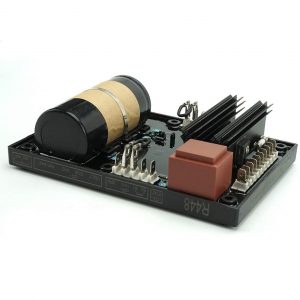 Automatic Voltage Regulators (AVRs)
AVR R448 Automatic Voltage Regulator For Generator of Leroy Somer
Key Features
- 100% Brand New And High Quality.
- Capable of withstanding harsh conditions and high vibration levels.
- Vibrations: -10Hz – a half-peak amplitude of 2mm; 10-100Hz – 100mm/s; +100Hz – 8g. Can operate in temperature extremes (-30c to +65c)
- We are confident the quality of our product is 100% qualified. If there is any question, feel free to contact us. We will offer the best service for you. Thank you!
- Click Here To Download R448 User Manual
SKU: n/a -
Automatic Voltage Regulators (AVRs)
AVR SX460 Automatic Voltage Regulator with Hard Shell for Stamford Generator
-47%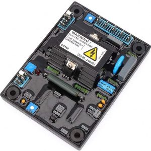 Automatic Voltage Regulators (AVRs)
AVR SX460 Automatic Voltage Regulator with Hard Shell for Stamford Generator
- SX460 AVR – Automatic Voltage Regulator – Exact Generic Replacement
- INPUT: Voltage: Jumper selectable 95-132V ac or 190-264V ac, Frequency: 50-60 Hz nominal, Phase: 1
- OUTPUT: Voltage: Max 90V dc at 207V ac input, Current: Continuous 4 A dc, Intermittent 6 A for 10 secs, Resistance: 15 ohms minimum
- Regulation: +/-1.0% * Thermal drift: 0.05% per deg. C change in AVR ambient
- Unit power dissipation: 10 watts maximum – Build up voltage4 Volts @ AVR terminals
- Soft Shell
- Click Here To Download SX460 User Manual
SKU: n/a -
Automatic Voltage Regulators (AVRs)
AVR R438 Automatic Voltage Regulator For Generator of Leroy Somer
-20%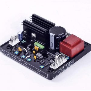 Automatic Voltage Regulators (AVRs)
AVR R438 Automatic Voltage Regulator For Generator of Leroy Somer
Key Features
- 100% Brand New And High Quality.
- The R438 voltage regulator module can be powered by AREP or PMG field excitation system
- Detection input: Voltage 95-480V AC; Power supply input: Voltage 40-150V AC three-phase for this automatic voltage regulator
- Material: metal and plastic material voltage regulator, lightweight, tough and durable, can be used for a long time
- Magnetic field output: when voltage input is 120V AC, max is 160V DC, max 10A for this brushless generator AVR
- 95-480V automatic voltage regulator is a must-have item for your brushless generator
- We are confident the quality of our product is 100% qualified. If there is any question, feel free to contact us. We will offer the best service for you. Thank you!
- Click Here To Download R438 User Manual
SKU: n/a
There are no reviews yet.